DIY SC1.5 Mod of
Logitech Quickcam Pro 3000 / 4000
There's a couple of pieces of advice that I would give to anyone looking to perform this procedure for the first time. Firstly, practice this procedure before attempting it on a good webcam. I ignored my own advice and destroyed a perfectly good QC Pro 4000 in the process. Luckily I was able to find a cheap QC 3000 on Ebay. Secondly, be patient. Don't rush anything. Sit down and think about what you are going to do before you actually do it.
The photos below are actually a mixture of Quickcam 3000 & 4000 shots. The internals are basically the same, the main difference being that the 4000 uses a different (better) CCD than the 3000. The instructions however apply equally to both the 3000 & the 4000.
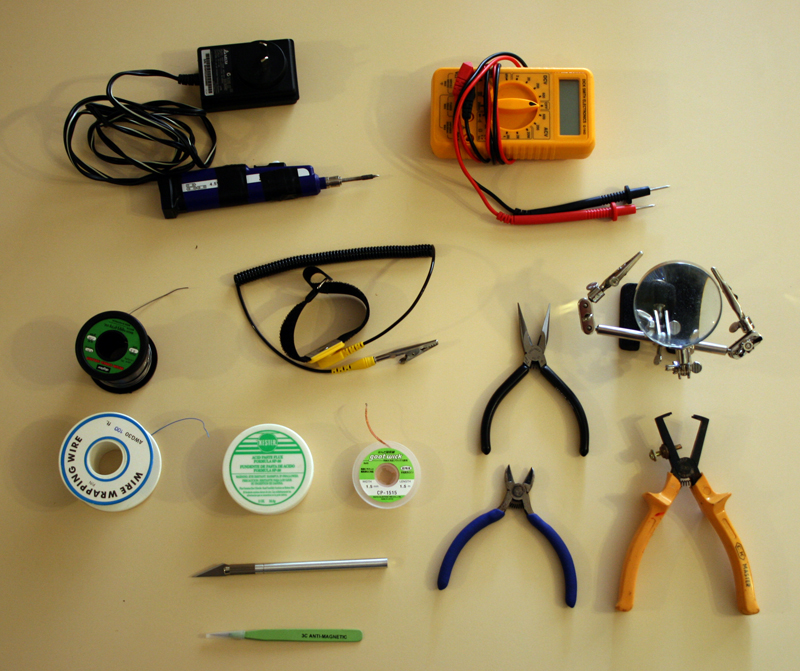
TOOLS USED
BUILDING THE EXTERNAL CIRCUITS
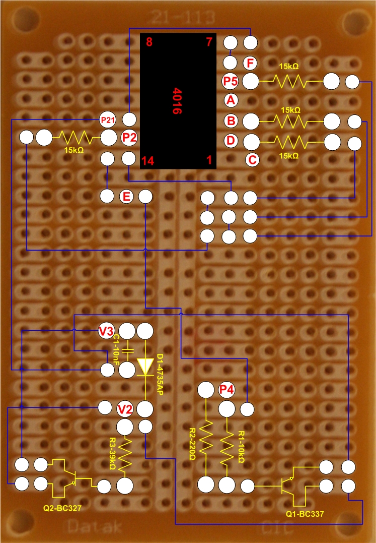
Above is the circuit that I built on a separate proto board to house the long exposure and amp off mod circuits. The board can be purchased from Dick Smith Electronics in Australia (Catalogue number H5608).
Note that I have indicated the points that need to be externally connected. These points refer to the letters used in Martin Burri's circuit diagrams (Px refers to Parallel connector pins). Also note that V1 in the amp off circuit is not required as I have connected it to another 5v point on the circuit board.
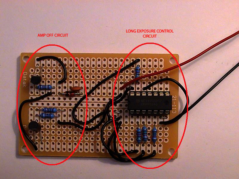
Example of a partially completed PCB.
WORKING ON THE WEBCAM

The above photo is of my original QC Pro 4000 which I used for normal planetary imaging. To kick things off, open the housing by undoing the screw which is accessed from the small hole seen in the side of the housing.

Once the camera has been opened, you can disconnect the microphone and the manual exposure button and remove the circuit board.

A virgin PCB. Untouched by soldering iron. This is where most of the work will be carried out.
.JPG)
View of the other side of the Logitech PCB with the CCD cover removed. Prior to the long exposure mod, I covered the LED with tape in order to remove any unwanted light during planetary imaging sessions.

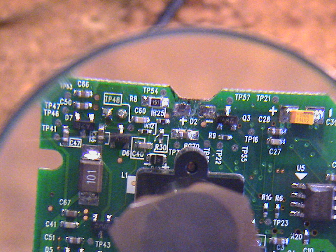
I used a small stand with a couple of alligator clips and a magnifying glass to perform the work on the Logitech PCB.
I found the simplest & safest way of lifting the pins on the Sony CCD Clock Driver chip was to carefully use a hobby scalpel to lever each leg away from the surface mount (no need to use a soldering iron to remove the surface bond). This needs to be done very slowly and methodically and should be practiced first if possible. Each leg took me about 5 minutes of gentle levering to lift.
Once the bond between the leg and the pcb surface has been broken, I lifted the legs and bent them over the top surface of the chip in order to simplify the process of soldering each leg to the blue wires as seen above. In order to simplify the soldering, I tinned the blue wires with solder first and placed a small amount of solder flux on the legs of the IC.
Each of the wires was then cemented to the top surface of the chip using a small dab of super glue (I tried using a glue gun but I found it to be very messy and the bond was not very strong).

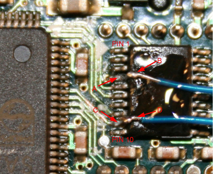
The above view shows the completed bypass surgery on the Sony CCD Clock Driver.
NOTE: Not shown here is the linking of pins 9 & 7 on the Sony chip (this can be seen in the diagram at the bottom of this page). As I discovered, based on the procedure I use (ie, lifting pin 9 as opposed to cutting the tracks) you lose the correct signal to pin 7. Pin's 7 & 9 need to be reconnected to provide the correct signal.
In order to remove any unwanted light during long exposures, I removed the LED from the Logitech PCB by desoldering the surface mount pads using a soldering iron and solder wick. The webcam will work perfectly well without the LED.
.JPG)
This picture shows the cover that sits over the CCD. You can see the IR filter still in place. I removed this filter in order to perform better imaging of Hydrogen alpha emission nebulas.
PUTTING IT ALL TOGETHER
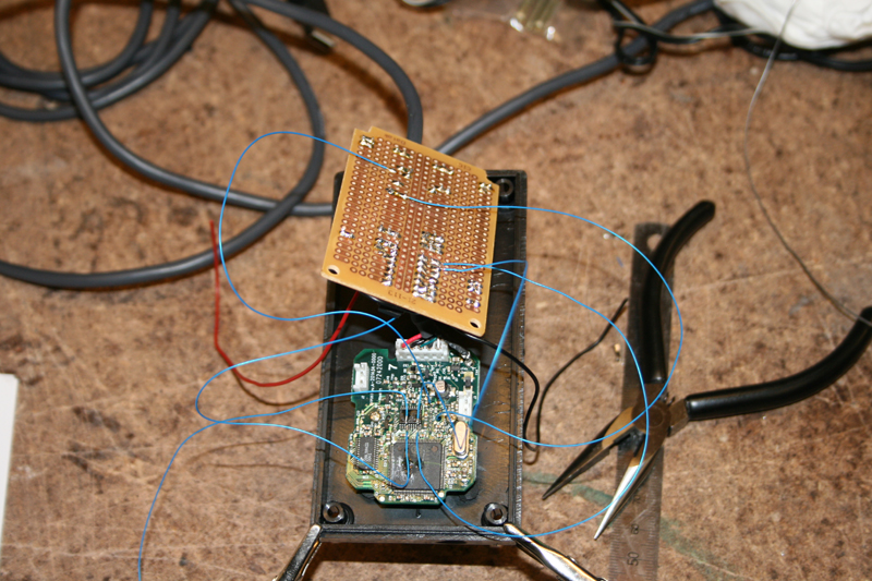
I drilled a hole in the lid of the project box and glued the flat surface of the CCD cover (at the base of the threaded section) onto the back of the project box lid.
As I mounted the external circuit board onto the bottom of the project box (facing up) I found that the safest way to connect the 2 boards together without placing any stress on the solder joints on the Logitech PCB was to position the external board as shown above and solder the connecting wires onto the under side of the external circuit board.
I then soldered the red (5 VDC) lead onto the red wire of the main connector. I did this by cutting away the rubber coating to expose the copper wire. I then used some flux to tin the exposed wire with solder before joining the 2 wires together.
To finish up, I soldered the black (Gnd) wire from the external circuit board onto the ground post of the Logitech PCB.


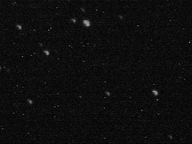
First Light!!
Captured with WX AstroCapture. 20 secs.
Oh No! What Happened? I'm not fussed with the hot pixels but what are those horizontal lines?
I posted a cry for help on the QCUIAG Yahoo Group and got a response from Martin Burri (many thanks Martin) indicating that I would need to connect pins 9 and 7 on the Sony chip (as originally indicated in his diagram).
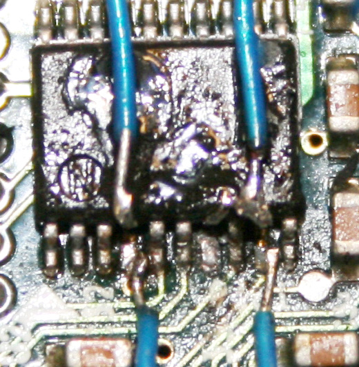
In the above image you can see my messy (but successful) attempt at connecting Pins 7 & 9 of the Sony CCD Driver together. They are usually connected via the pad but seeing my mod lifts pin 9, the pad no longer provides this connection. It's quite easy to do this. You just need to do it slowly and patiently.
Second Light!!!
Success (M4 - 15 x 15sec images with dark frames subtracted).
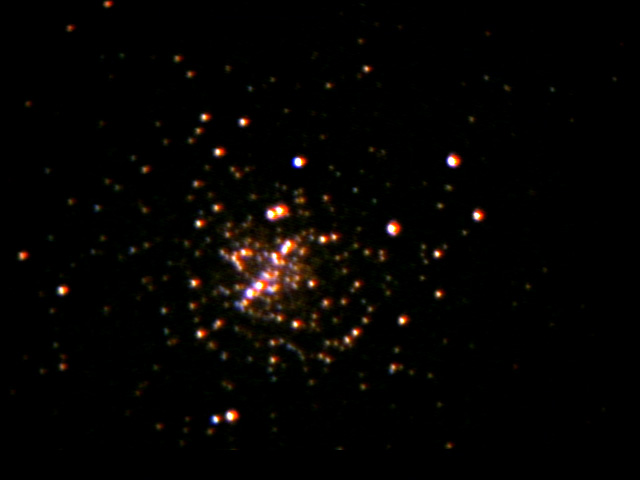
Not a great imaging camera, but it should do nicely as a guide cam.
![]()
![]()
![]()
![]()
![]()
![]()
![]()
![]()
![]()
![]()
![]()
![]()
![]()
![]()